JFF45
Members
-
Joined
-
Last visited
Reputation Activity
-
 JFF45 got a reaction from Rumcajs in RE4R03A Nomad valve body overhaulIt's a shed job alright. Here's where I'm doing the trans
-
JFF45 got a reaction from BigGQWesty in RE4R03A Nomad valve body overhaulI know this will have limited interest but I noticed that the RE4R03A rebuild threads don't go into much detail on how to overhaul the valve body. This one happens to be a Nomad valve body that I bought used from a trans that had suffered an oil pump mishap so it had to be completely dismantled to make sure it was spotless. First you need to print out the relevant pages of the FSM and preferably put them under plastic. I also have the pages for the full trans overhaul in there as well. Prepare a nice clear workspace for yourself. I have this fairly big steel leg laminated table I got from the dump for $10. I used black plastic initially but it didn't like the ATF so I had to work directly on the table. It's really important when doing this kind of work, where parts need to go back in the correct order, to have some way of clearly and logically laying out those parts. I simply cut a length of aluminium flashing (Bunnings) and used some stainless rods I had to form a corrugated sheet. It bends easily by hand and takes 5 minutes to make. Simply follow the FSM and you can't go wrong. Wholesale Autos, who supply these valve bodies, make there own laser cut separator plate. Most shift kit makers (TransGo, Superior, etc) supply drill bits to modify the plate so this is obviously a more professional approach. The upper body has the majority of the valves so we start there. The pressure regulator (2nd from top) almost certainly has been modified judging by the red coloured spring. Most shift kits modify it as well. 5th from the top and 3rd from the bottom are machined parts that don't match the FSM. These are called Shuttle shift valves and originally they move against a spring with an end plug for the locking pin. These have the pin slot machined in the ends so they are effectively locked solid which is the obvious reason they no longer have a spring either. Here's a clearer pic of the parts.. Then we do the lower body. Same system, line the bits up in the corrugations in the order and sequence in which they're removed.
I've now fitted this valve body to my TB45E in place of the valve body in which I fitted a TransGo shift kit a few years ago. This one might be slightly more precise in the 2-3 change but there's not much difference otherwise.
A TransGo shift kit can be bought for ~$140 and I think the Nomad exchange valve bodies are now > $1000.
I'm currently doing a complete rebuild of a RE4R03A from a TB45E but I'm building it to Infinity Q45 (the 4.5 lt V8) specs with the extra clutches. I'll do a thread with pics when I've finished it.
-
JFF45 got a reaction from Rumcajs in RE4R03A Nomad valve body overhaulI know this will have limited interest but I noticed that the RE4R03A rebuild threads don't go into much detail on how to overhaul the valve body. This one happens to be a Nomad valve body that I bought used from a trans that had suffered an oil pump mishap so it had to be completely dismantled to make sure it was spotless. First you need to print out the relevant pages of the FSM and preferably put them under plastic. I also have the pages for the full trans overhaul in there as well. Prepare a nice clear workspace for yourself. I have this fairly big steel leg laminated table I got from the dump for $10. I used black plastic initially but it didn't like the ATF so I had to work directly on the table. It's really important when doing this kind of work, where parts need to go back in the correct order, to have some way of clearly and logically laying out those parts. I simply cut a length of aluminium flashing (Bunnings) and used some stainless rods I had to form a corrugated sheet. It bends easily by hand and takes 5 minutes to make. Simply follow the FSM and you can't go wrong. Wholesale Autos, who supply these valve bodies, make there own laser cut separator plate. Most shift kit makers (TransGo, Superior, etc) supply drill bits to modify the plate so this is obviously a more professional approach. The upper body has the majority of the valves so we start there. The pressure regulator (2nd from top) almost certainly has been modified judging by the red coloured spring. Most shift kits modify it as well. 5th from the top and 3rd from the bottom are machined parts that don't match the FSM. These are called Shuttle shift valves and originally they move against a spring with an end plug for the locking pin. These have the pin slot machined in the ends so they are effectively locked solid which is the obvious reason they no longer have a spring either. Here's a clearer pic of the parts.. Then we do the lower body. Same system, line the bits up in the corrugations in the order and sequence in which they're removed.
I've now fitted this valve body to my TB45E in place of the valve body in which I fitted a TransGo shift kit a few years ago. This one might be slightly more precise in the 2-3 change but there's not much difference otherwise.
A TransGo shift kit can be bought for ~$140 and I think the Nomad exchange valve bodies are now > $1000.
I'm currently doing a complete rebuild of a RE4R03A from a TB45E but I'm building it to Infinity Q45 (the 4.5 lt V8) specs with the extra clutches. I'll do a thread with pics when I've finished it.
-
JFF45 got a reaction from Rumcajs in Thermostatic fan install to 2000 zd30 intercooler How to do it correctlyHere's an option for IC fan control.
http://www.autospeed.com/cms/A_112617/article.html
It's what I'll be using for the IC fan control for my turbo install. I found one on Ebay for a little over $20 delivered..
-
JFF45 got a reaction from Rumcajs in DIY - Winch mount + winch install with alloy bumperEveryone seemed to think it was a good idea to check the grease in the gearbox before installing it so that's what I did. Happy to find that it was plentiful..
Very simple to take apart..
-
JFF45 got a reaction from Rumcajs in DIY - Winch mount + winch install with alloy bumperThis is how I did the protection for under the radiator and replaced the plastic air deflector.
I wanted to copy the original plastic item as closely as possible, especially the angle, so I made a 12mm square frame first then gusseted the corners..
Had to buy the 3mm steel sheet and cut it to size with my Ebay plasma cutter.
This is my spray booth..
Fits exactly as planned..
-
JFF45 got a reaction from Rumcajs in DIY - Winch mount + winch install with alloy bumperSolenoid and cabling
The collective wisdom says to get the solenoid up out of the weather. There's no room to clip it onto the winch rails anyway.
Very simple to take apart and remove the controller plug.
Part of the reason these winches are cheap is that the wiring is not real thick. If the winch is made to work hard, you'll get voltage drop and, consequently (Ohm's law, remember), increased current.
Original wire appears to be 2 gauge (<35mm2). I went for 0 gauge (~50mm2) from my local Jaycar store.
Got the lugs from Ebay, $26 for pack of 10 delivered. A lot cheaper than Supercheap but Jaycar prices are pretty reasonable.
Got this 12 ton hydraulic hex crimper also from Ebay for $54.90 delivered.
It worked well but only after I used the 35mm dies following the 50mm dies. The 50mm dies just weren't tight enough.
I found this when I soldered the opening as corrosion-proofing and the solder wicked through the crimp. With the 35mm dies I have a good gas-tight crimp.
I made up a small bracket and fitted the solenoid alongside the battery. I couldn't find a better place to put it. It's ideal for cable lengths and cable routing.
I need to change it so it just clips in there in case I need quicker access to the relays.
Had to make up this brass spacer to allow the cable to pass over the solenoid.
Routed the cabling through the hole where the horn wire was. Added some loom tube to the hole over the original plastic ring. I made the bracket to pass the cables over the bumper mount and covered it with 3 layers of heatshrink.
-
JFF45 got a reaction from Rumcajs in DIY - Winch mount + winch install with alloy bumperI discarded the original TI stainless barwork & bumper and found an alloy bar on Gumtree for $250.
Now to fit the alloy bar and adjust the fairlead.
I did the cutout for the fairlead with an air body saw fitted with a broken hacksaw blade.
.. and no, the rope doesn't hang there now. It was just for the pic
-
JFF45 got a reaction from admin in DIY - Winch mount + winch install with alloy bumperI discarded the original TI stainless barwork & bumper and found an alloy bar on Gumtree for $250.
Now to fit the alloy bar and adjust the fairlead.
I did the cutout for the fairlead with an air body saw fitted with a broken hacksaw blade.
.. and no, the rope doesn't hang there now. It was just for the pic
-
JFF45 got a reaction from GQ Beast in DIY - Winch mount + winch install with alloy bumperI bought a Supercheap Ridge Ryder 12000lbs winch when they were having one of their 35% off sales. Paid $565 for it.
This thread is about how I made my own winch mount, installed the winch and made some 3mm plate protection under the radiator and extended it to replace the factory plastic air deflector.
I did this to fit with the factory alloy bumper bar.
I started with the idea that I wanted to use as much metal scrap as I could find in my shed.
Main component is a length of 50 x 75 x 3mm wall RHS with bits of 6mm flat bar added to it.
What I wanted here was to have the winch mounted 25mm lower than the usual universal mount plates that people often use which sit across the 2 chassis rails.
I also needed a lower point to attach the underbody protection that is part of this excercise and the bottom of the RHS is ideal - as you'll see further down.
The fairlead is mounted on a removable bracket because I have to be able to adjust it for the cutout in the alloy bumper.
I welded on these tabs with nuts to fix the 3mm plate.
While I had the front off I opened the LH chassis rail to insert a plate with 2 nuts for the LH recovery plate. I fed the 3rd nut in with a telescopic magnet
I'll continue with the winch install tomorrow..
-
JFF45 got a reaction from GQ Beast in DIY - TB45E turbo installCatch can..
Time will tell if this is really necessary on a reasonably low mileage petrol engine but I had to modify one the original PCV hoses anyway so why not run it through a device that could condense any oil vapour.
On top of that, it adds a bright shiny item under the bonnet
PCV mod is pretty easy to do on the 4.5. You leave the original rear hose to the PCV valve in place - although I did shorten the elbow for more clearance with the fan. The PCV valve will act as a check valve under boost.
The front hose on the rocker cover is routed to the catch can and another hose from the catch can to the intake pipe between MAF and turbo compressor.
Connected in this manner, the PCV valve works normally under vacuum while the intake air for the engine is drawn through the catch can from the intake pipe between MAF and turbo compressor where it has already been measured by the MAF.
Under boost, the PCV valve will close and any pressure building in the crankcase can exit via the air intake on the rocker cover where it will pass through the catch can and into the pre-turbo intake again.
As the meerkat would say, simples!
This is the $38 Ebay knock off I bought. It's cheap because it has nothing in it which also means it won't catch much because the vapour will go in and straight back out via the 2nd hole.
It does have a sight tube on the side and an oil drain plug.
Very easy to make this work a bit better. We need a baffle to force the vapour to take a longer route. I had some scrap stainless sheet offcuts from my DIY heatshield so I made this:
We also need some medium to condense any oil vapour. Don't listen to those who say use steel wool - it crumbles into fine steel dust that is easily airborne.
I had some Bunnings aluminium flashing left over so I cut a few pigtails with tin snips. These are big enough so they can't get sucked into the system and have enough surface area to condense the vapour - that's my theory anyway..
Almost forgot, this is where I fitted it..
-
JFF45 got a reaction from GQ Beast in DIY - TB45E turbo installBonnet scoop..
I would have preferred not to do this but with a top mount air-to-air IC you don't have much choice.
This is the Ebay 'Navara style' fibreglass jobbie for $115. Not the real cheapie plastic one nor the higher end $300 - $400 article.
It covers the IC pretty well.
I painted it with rattle cans (we're talking budget install here, remember..)
I took the bonnet off to cut it and fit it. It's very slightly off-colour depending on the angle and sunlight but in real life you don't really notice it.. and it is a 13 year old vehicle after all..
More to come...
-
JFF45 got a reaction from GQ Beast in DIY - TB45E turbo installIntercooler continued..
In order to fit that size IC over the throttle body, you have to move the IACV because the connector plug sits too high.
My thanks once again to JoseM from Panama for this idea. It was his TB45E turbo build pics that showed me that a 76mm thick IC could be fitted over the throttle body.
I made this adapter from some 3mm plate and a short length of 25mm square tube. This allowed me to have the IACV down behind the inlet manifold.
I brazed up some copper pipe & elbows to be able to use the original air feed pipe in the meantime. Also, the wires need to be lengthened.
It's actually light grey but the iPad camera turned it blue..
Here's a pic of the fan mounting bolts. 6mm welded to the frame with nuts and washers fitted first.
This is the clearance under the fan. You'll need to use elbows on the PCV outlets to maintain the clearance.
Small detail on the IC.. I added 20 x 25 x 1.6mm aluminium angle front and rear with pop rivets to have a flat surface for the sealing foam.
Bonnet scoop next..
-
JFF45 got a reaction from GQ Beast in DIY - TB45E turbo installIntercooler:
This has been the most challenging and rewarding phase of the excercise so far.
My research convinced me that there was nothing more important than keeping intake air temps down so that meant fitting the biggest IC I could. It had to be top mount because of the winch and auto trans coolers not allowing for front mount fitting.
This in turn meant I had to use a low mount manifold to leave enough room on top.
As this is a budget install, no point in throwing big money at it. Ebay is my friend so I got this:
I knew it was going to be close to the bonnet and I didn't want it to shake with the engine. I also wanted a fan underneath it so I decided the best way was to make a cradle that fixed it to the bodywork.
The cradle would also serve to better mount the fan rather than bolt the fan directly to/through the IC.
Here are some pics of my first attempts using too many silicone elbows which would have meant too many hose clamps and the whole thing a bit too thick where it fits to the throttle body.
So I decided it would be more practical (and look better) if I fabricated as much of the intake piping as possible from exhaust pipe. This would allow me to mount the BOV a bit closer to where it crosses over to the pre-turbo air intake.
I had bought a whole bunch of different sizes and bends of 2.5", 2.75" & 3" mandrel bent 1.6mm pipes from Ebay.
I did the fine grinding to get angle right with an old belt sander I haven't used in years.
Added the air feed pipe for the IACV and welded an 8mm nut on for the temp sensor for the fan switch.
Added the 25mm pipe for the BOV.
This is where it's at at the moment
This the fan I chose. It's a Davies Craig 12"
Here's the fan fitted into the IC cradle.
More to come...
-
JFF45 got a reaction from GQ Beast in DIY - TB45E turbo installEngine management:
I've had an Xede piggyback on my N/A setup for a while now. I was lucky enough to pick it up from US Ebay for a little over $100 incl. Postage.
Here are a couple of Autospeed articles about the Xede and some other choices.
http://www.autospeed.com/cms/article.html?&title=The-Xede-Interceptor&A=1545
http://www.autospeed.com/cms/article.html?&title=Engine-Management-Interceptors-Part-Two&A=2901
What I liked about it is that the Xmap tuning software is free from Chiptorque - you're not restricted to only authorised sellers/tuners as with Unichip, for example.
The timing profile file for the 4.5 is also free as is the wiring diagram from the Chiptorque website.
Although I didn't buy it from them new, I got excellent replies from emails to Chiptorque and they even sent me a tuning map they had done on their dyno with a 4.5 with exactly the same exhaust mods as mine.
I even got some free advice from their head tuner on using a MAP sensor as the load parameter for the fuel and timing maps.
For the low boost I'll be running, the Xede should handle it. It can pull up to 10 degrees of timing and can alter the MAF signal sufficiently for my needs. There was a recent thread elsewhere where a supercharged 4.8 put out 185 kW @ 5 psi boost using an Xede piggyback.
Another advantage of the piggyback is that you retain all the principal functions of the factory ECU.
To be able to detect when your under boost you must have a MAP sensor. Some engine management systems have them included inside the case.
For the boost I'll be running, a 2 bar MAP sensor is all I need so I bought a GM type from Ebay and mounted it here:
I've taken the manifold pressure for the MAP sensor from the cruise control vacuum hose then a T from that to inside for the boost gauge.
The MAP sensor needs a 5v feed so I've taken that off my Innovate SSI-4 data logger. I also bought a cheap Ebay 12v to 5v converter just in case.
The MAP is wired to both my data logger and the Xede at the moment but I'm still using MAF & TPS for the load signal with my N/A setup.
Fuel:
When the inlet manifold is under boost, the fuel pressure will need to rise to help the injectors open against the boost pressure.
I fitted a boost referenced fuel regulator that will increase the fuel pressure at a 1:1 ratio.
I'll try it first with the factory 270cc injectors but I did buy a set of 370cc RB25DET injectors from Gumtree for $30 that I can swap in if the originals max out. They shouldn't at that boost level.
I have a Bosch in line fuel pump I can also fit if required otherwise I'll get a Walbro to replace the original pump.
More coming...
-
JFF45 got a reaction from GQ Beast in DIY - TB45E turbo installI've noticed elsewhere that these TB45E turbo builds usually generate a fair bit of interest so I thought I'd add mine and explain with pics how I went about it.
I've had this vehicle for 7 years now and I've gone through the usual stages of extractors + 2.5" exhaust system and finally added an Xede piggyback to make some changes to fuel & timing.
Each of these changes adds a little more performance but, as I'm hoping to hook up a fairly heavy caravan one day for the traditional lap, I really thought I needed a bit more power in reserve to cover those overtaking situations that many talk about.
I had thought about selling it and getting a 4.8 but the old 4.5s aren't worth a lot these days even if mine is a Ti with only 132,000 kms on it. I've done a fair bit of work on mine and just knew I wouldn't find a reasonably priced 4.8 in the same nick.
Then there's the fact that I have a heap of spares for the 4.5 (even a spare auto trans), I have the manuals & PDFs, etc and they are a far easier engine to work on than the 4.8 e.g. tappet adjustment is a $300 dealer job.
So, what about power.. the standard 4.8 puts out ~ 130 - 135 rwkW. Most turboed 4.5s can be made to reliably produce ~150 kW under 7 psi. I'm planning to run with the standard internals (don't see any point in opening a 130k kms engine) and limit the boost to 0.3 bar (~4.5 psi). That should give me what I need and still be reasonably kind to the auto trans. I have already fitted a TransGo shift kit to the auto and done the line pressure solenoid mod with a 2k ohm resistor as well as an additional big Davies Craig trans fluid cooler. I have a temp gauge on the trans and run Castrol TransmaxZ in it. My research tells me it should hold up if I don't drive it like an idiot.. at 68 not much risk of that..
Cost.. I did a bit of research and decided that I could keep this project under $4k if I do as much as possible myself. I was a mechanic in a much earlier life (70s - early 80s) and have a pretty well equipped shed. I have a welder and plasma cutter, a press, etc so just about all I need for light fabrication.
There was no way I could have swapped into a 4.8 in the same condition for that kind of money..
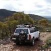
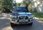
This is the vehicle I'm starting with..
These are my costs so far..
One thing I've done throughout this project is always keep the vehicle drivable. Even making up the IC frame, I could always get the airbox and intake pipes, etc back on within a half hour if I needed to use it.
You can't use the TB45E airbox so why not use a different Patrol airbox that drops straight into existing holes and lines up with the original hole in the inner guard where the snorkel enters.
To do that, you need to move the charcoal canister. If you throw it away, you won't get complianced.
I moved mine down behind the bumper. I welded up a simple bracket from some scrap flat bar. Obviously, you'll need longer vacuum hoses.
The clean air intake for the canister must be removed from where it goes into the inner guard. I routed it up behind the left headlight and fitted a small air filter to it.
An important point here is that you'll need to fit check valves into the 2 vacuum hoses to stop pressurising the canister under boost.
Here's the TD42 airbox fitted in place of the charcoal canister. The 3" silicone elbow will point down towards the turbo compressor once it gets fitted.
The mod for the cobra head is easy. There are threads elsewhere where people have done some better mods with flanges, etc but I kept mine simple and just cut the original outlet off with a Dremel and inserted a short length of 3" exhaust pipe with Sikaflex
and 4 screws.
I cut the flat flange off the intake and passed a 3.5" short silicone hose through the hole to join the airbox intake to the snorkel. You need to pop out the left indicator to tighten the hose clamp inside the guard.
More coming...
-
JFF45 got a reaction from GQ Beast in New member from QLDGreetings from QLD where it's a beautiful sunny Winter's morning.
My name is John and I have a 2001 GUII 4500 Ti that I've done some minor changes to and that is a bit of a hobby now in retirement.
I'm currently doing my own GT35/40 turbo install (from a BA Falcon XR6T) where I'm doing most of the work myself.
I'm a fair way into it and would like to do a build thread here hoping it might interest other 4.5 owners.